

Perception [BETA]
Note
This is a BETA feature.
Ouster SDK 1.0 introduces the Ouster Perception API, which includes a detection engine interface and implementation to add objects (i.e. features derived from lidar data) to LidarFrame or FrameSet.
At this time, Ouster SDK includes a single detection engine implementation that performs clustering
on the lidar data present in a LidarFrame or FrameSet and adds an
Object for each cluster.
Future releases will add new engines, including those that do object classification.
Key capabilities
Cluster-based object detection: Run the built-in
DetectionEngineon live or recorded sources to produce cluster-derived Object instances for each frame.OSF persistence for perception outputs: Save frames, detected objects, and related metadata into OSF for reproducible offline workflows.
Metadata-aware datasets: Create and attach metadata such as, class maps, through FrameSetSourceMetadataSet via API, and persist it in OSF; CLI preserves existing metadata during OSF save.
Integrated visualization: Inspect detections with
ouster-cli ... detect ... vizor in Python using SimpleViz.
You can find the getting started guide for CLI at ouster-cli.
Applications
Common applications for Perception in the SDK include:
Rapid obstacle discovery and scene triage: Accelerating early-stage development in robotics prototypes by quickly isolating critical objects.
Downstream stack integration: Extracting obstacles, bounding boxes, or clusters to serve as clean inputs for tracking, localization, and path-planning modules.
Dataset curation and annotation: Saving model inferences and detections directly within OSF files to streamline downstream labeling and data engineering.
Baseline benchmarking and regression testing: Evaluating model performance metrics consistently across historical recordings and diverse physical sensor configurations.
Visualization and situational awareness: Overlaying perception data for client demos, remote operator interfaces, and visual QA workflows.
Core concepts
Object — a generic object, represented by a bounding box,
object_to_bodyandbody_to_worldposes, velocity, classification, a timestamp, and user-definable set of properties represented by strings.DetectionConfig — base configuration for detection engines. Subclasses such as ClassicDetectionConfig provide settings for the classic cluster-based engine.
DetectionEngine — a base class that declares virtual methods for modifying (e.g. by adding objects to) LidarFrame and FrameSet.
ClassMap — A mapping from integers to strings, meant to map
Object::class_idto a string description.ClassMapSet — A mapping from strings to
ClassMapinstances, allowing users to specify different descriptions forObjectinstances derived from differentDetectionEngine.FrameSetSourceMetadataSet — A container for instances of
ClassMapSetand other metadata a user may want to associate with aFrameSetSource. Currently, because OSF is the only format that supportsLidarFrameandFrameSet, the OsfFrameSetSource is the only implementation that supports metadata.
For detailed type definitions and end-to-end examples, see API workflow for application integration, custom logic, and programmatic control.
For fast iteration, using CLI commands, to dataset generate and vizualize data refer to CLI workflow.
Coordinate Frames
The SDK represents all spatial relationships through a chain of named coordinate frames connected by SE(3) transforms. An SE(3) transform is a 4x4 matrix holding a 3D rotation and a 3D translation; it moves a point from one frame into another without changing the object’s shape or size.
Each transform is named a_to_b, which means it takes a point’s coordinates in frame a and gives
them back in frame b. Transforms are combined by multiplying their matrices (right-to-left), so a
two-step hop a → b → c is:
To turn a raw measurement into a world point, the SDK walks the chain lidar → sensor → body
→ world. Every transform can also be inverted, so you can travel the chain in either direction.
Every edge is either static — a single time-invariant matrix that is the same for every frame in a recording — or dynamic — a timestamped sequence of matrices that is interpolated (spherical-linear for the rotation, linear for the translation) to whatever time you ask for. The four kinds of transform are:
Firmware calibrated (static) — the sensor’s internal optics and IMU geometry. These come from the per-unit factory calibration shipped in the sensor metadata, so they are accurate to the individual sensor and never change over its lifetime.
Per-mounting configuration (static) — how each sensor is positioned on the platform. Supplied once by the user or a calibration routine, this is the piece that lets several independently-calibrated sensors agree on a single shared
bodyframe; it changes only if the hardware is physically re-mounted.Per-detection snapshot (static) — a detected object’s placement relative to
body. Each object stores its own matrix, so the value differs from object to object, but for any single detection it is one fixed pose rather than a trajectory.Dynamic trajectory (dynamic) — the platform’s ego motion through the
worldframe. This is the only quantity that evolves as the recording plays.LidarFrame::body_to_worldstores the full timestamped trajectory, one matrix per lidar column; andObject::body_to_worldis a single matrix sampled from that trajectory at the object’s detection timestamp.
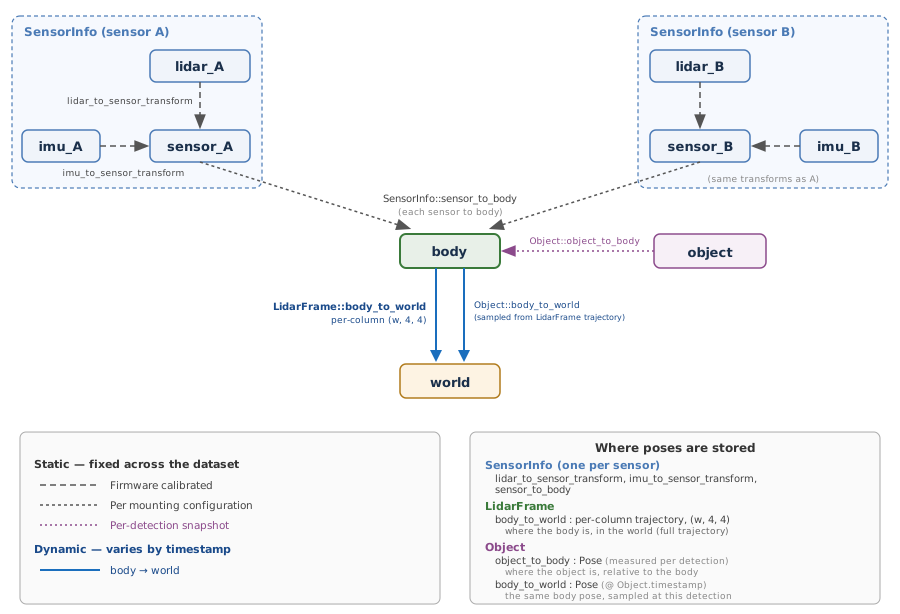
SDK pose graph: coordinate frames and transforms
The key coordinate frames used in this pose graph are:
Frame |
Description |
|---|---|
|
Raw lidar optics frame, where each laser beam originates. An internal frame, brought into the
|
|
Lidar measurement frame. A fixed, hardware-calibrated frame defined by the sensor’s internal geometry.
Transformed to the sensor housing frame via |
|
Sensor housing frame. The external coordinate system of one physical sensor unit. Each sensor on the
platform has its own |
|
IMU measurement frame. Related to the sensor frame by the fixed |
|
The single common reference frame shared by all sensors mounted on the platform; measurements from every sensor are fused here. |
|
Object-local bounding box frame. The origin is at the center of the detected object’s bounding box,
with axes aligned to the object’s principal directions. |
|
Sequence-local world frame. A fixed reference frame for a recording session; typically the body frame
at the start of the sequence. The dynamic |
All of these frames are right-handed. For the exact axis directions and origins of the Ouster
sensor, lidar, and imu frames, see the Ouster sensor coordinate frame documentation .
Where poses are stored
Transforms are owned by three data structures:
SensorInfo (one per sensor):
lidar_to_sensor_transform,imu_to_sensor_transform, andsensor_to_body.LidarFrame: dynamic
body_to_world()ego trajectory, one SE(3) per lidar column (shape(w, 4, 4)).Object: per-detection
object_to_bodyandbody_to_world.body_to_worldis sampled fromLidarFrameatObject.timestamp, making each object self-contained.
Object world pose is computed by composing the two Object pose fields (both stored on the Object itself):
In code: object_in_world = object.body_to_world * object.object_to_body
The velocity field of an Object is expressed in the world frame.