

Using the API
Creating zones
The LiDAR can monitor zones that are unobstructed and within its field of view. Conversely, a configuration that specifies a zone outside the field of view is invalid. Additionally, if a zone is behind an obstruction or occlusion, the LiDAR will not be able to determine whether an object occupies it. However, the LiDAR will report the number of points that occlude a zone, which helps indicate whether the sensor can monitor the zone effectively.
Users can specify zones either using 3D meshes that the sensor renders to an internal image-based representation, or directly as range image pairs (bypassing the rendering step.) The following sections describe both approaches, as well as how to specify the zone’s criteria for triggering.
Tip
The SDK currently supports loading meshes from STL files. A large number of tools, such as Blender can produce STL files from 3D models.
Defining a zone from a 3D mesh
When the user uploads a 3D mesh (e.g., in the form of an STL file) as part of a zone’s configuration, the sensor renders this geometry into a pair of near/far distance images that it uses during each frame to determine which LiDAR measurements are within the zone. This rendering process checks the intersections between each LiDAR beam and the 3D mesh. Because of this, the LiDAR also requires that each zone’s geometry meets some basic criteria.
Tip
Zone Monitor assumes meter units for mesh vertex coordinate values. Although the STL format does not support a scale factor, many 3D modeling tools allow for one when exporting a model to STL. When exporting STL files for Zone Monitor zones, ensure that the scale factor is set correctly so that the geometry is the correct size in meters.
First, each of the LiDAR’s beams should intersect the 3D geometry no more than two times. If a beam intersects the geometry two or more times, the LiDAR considers the portion between the closest and furthest intersections to be inside the zone and all other portions outside. If a beam intersects the geometry exactly once, then the LiDAR considers the area between the sensor and the intersection to be inside the zone and all other portions outside. Importantly, this means that the LiDAR cannot monitor all 3D geometries. The Visualization section later in this document describes how to visualize any potential difference between the specified geometry and what the sensor can monitor.
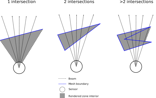
A top-down view of some example mesh shapes and how they affect rendering results
Another important criterion for a valid zone configuration is that the number of points required for the sensor to trigger the zone must not be greater than the number of beams that intersect it. (If this criterion is not met, the LiDAR never triggers the zone because the number of LiDAR measurements would always be fewer than the number of points the configuration specifies for triggering.)
Defining a zone from a pair of depth images directly using ZRB format
Users can also specify a pair of images representing the near and far ranges of the zone directly (rather than having the sensor render them from a 3D mesh.) The SDK provides an API for doing this, including saving the results to a ZRB file - a proprietary format for encoding a zone as a near/far image pair. Using this approach is subject to some requirements and limitations:
The near/far images are 32-bit unsigned integer images representing distance in millimeters.
The near/far images must be in the LiDAR’s coordinate frame.
The near/far images for a zone must have the same resolution.
The near value for a pixel must always be less than or equal to the far value for the corresponding pixel.
The resolution must be the same for all images within a given zone set.
Specifying zone triggering criteria
Zones have several parameters that determine how and when they trigger. The most important of these is the number of points that must be present within the zone for it to trigger. This parameter is an integer. Other parameters include the frame count, which specifies the number of consecutive LiDAR frames that must meet the triggering criteria before the zone triggers, and the mode, which specifies whether the zone triggers when the number of points within it is greater than or less than the specified number of points. Here is a complete list of zone parameters:
mode- eitherOCCUPANCYorVACANCY.point_count- when the mode isOCCUPANCYthere must be this many points or more within the zone for it to trigger; when the mode isVACANCYthere must be fewer than this many points within the zone for it to trigger.frame_count- the number of consecutive LiDAR frames that must meet the triggering criteria before the zone triggers.label- an optional string label for the zone, useful for identifying zones in application code.
Refer to the Python Zone API reference for more information about these parameters.
So far, we’ve described how to define a single zone’s geometry and triggering criteria. The following sections will explain how to programmatically create a complete set of zones from either mesh-derived or image-derived zone geometry and upload it to the sensor.
Creating a ZoneSet
The Python class ZoneSet are for storing a complete Zone Monitor configuration consisting of multiple zones, their geometry, and their associated metadata.
Specifying a sensor-to-body transform for the ZoneSet
The ZoneSet requires a sensor-to-body transform that specifies the pose of the sensor relative to the zones. Using this transform allows creating zone geometry that is defined in a body frame (e.g., the vehicle frame) rather than the sensor frame. This is useful because the zones often correspond to physical features of the body (e.g., the sides of a vehicle) rather than features of the sensor itself. Using an identity matrix for the transform means that the zones’ geometries use the sensor’s coordinate frame.
The Ouster Sensor Docs contain a detailed description of the sensor’s coordinate frames.
Important
The zone geometry must remain fully or partially within the sensor’s FOV after applying the sensor-to-body transform; otherwise, the zone set is invalid.
Creating a ZoneSet using the SDK
The following examples describe how to create and define zone sets that the LiDAR can render from STLs or directly from ZRBs, respectively.
In both cases, the SDK writes the ZoneSet as a zip file, which the sensor accepts as an upload either via the HTTP API or from the web UI.
Start by importing the necessary modules:
Imports
from ouster.sdk import core
using namespace ouster::sdk;
The following examples show how to create a zone set from STL meshes or directly from ZRB range images.
Creating an STL zone set
# Define a zone from STL file
stl_0 = core.Stl(os.path.join(data_dir, "0.stl"))
stl_0.coordinate_frame = core.CoordinateFrame.BODY
zone_0 = core.Zone()
zone_0.stl = stl_0
zone_0.point_count = 10
zone_0.frame_count = 1
zone_0.mode = core.ZoneMode.OCCUPANCY

# Define another zone from STL file
stl_1 = core.Stl(os.path.join(data_dir, "1.stl"))
stl_1.coordinate_frame = core.CoordinateFrame.BODY
zone_1 = core.Zone()
zone_1.stl = stl_1
zone_1.point_count = 20
zone_1.frame_count = 2
zone_1.mode = core.ZoneMode.VACANCY

# Create a zone set and add the zones
zone_set = core.ZoneSet()
zone_set.sensor_to_body_transform = np.eye(4)
zone_set.zones = {0: zone_0, 1: zone_1}
zone_set.power_on_live_ids = [0, 1]

# Print the JSON representation of the zone set
print(zone_set.to_json(core.ZoneSetOutputFilter.STL))

# Write out the zone set to a zip file
zone_set.save(zip_path, core.ZoneSetOutputFilter.STL)
// Define a zone from STL file
core::Stl stl_0(data_dir + "/0.stl");
stl_0.coordinate_frame = core::Stl::CoordinateFrame::BODY;
core::Zone zone_0{};
zone_0.stl = stl_0;
zone_0.point_count = 10;
zone_0.frame_count = 1;
zone_0.mode = core::Zone::ZoneMode::OCCUPANCY;

// Define another zone from STL file
core::Stl stl_1(data_dir + "/1.stl");
stl_1.coordinate_frame = core::Stl::CoordinateFrame::BODY;
core::Zone zone_1{};
zone_1.stl = stl_1;
zone_1.point_count = 20;
zone_1.frame_count = 2;
zone_1.mode = core::Zone::ZoneMode::VACANCY;

// Create a zone set and add the zones
core::ZoneSet zone_set;
zone_set.sensor_to_body_transform = core::mat4d::Identity();
zone_set.zones = {{0, zone_0}, {1, zone_1}};
zone_set.power_on_live_ids = {0, 1};

// Print the JSON representation of the zone set
std::cout << zone_set.to_json(core::ZoneSetOutputFilter::STL) << std::endl;

// Write out the zone set to a zip file
zone_set.save(zip_path, core::ZoneSetOutputFilter::STL);
Creating a ZRB zone set
sensor_to_body_transform = np.eye(4)

# Define a zone from a pair of images
zrb = core.Zrb()
zrb.near_range_mm = 10_000 * np.ones((sensor_info.h,
                                      sensor_info.w), np.uint32)
zrb.far_range_mm = 100_000 * np.ones((sensor_info.h,
                                      sensor_info.w), np.uint32)
zrb.serial_number = sensor_info.sn
zrb.beam_to_lidar_transform = sensor_info.beam_to_lidar_transform
zrb.lidar_to_sensor_transform = sensor_info.lidar_to_sensor_transform
zrb.sensor_to_body_transform = sensor_to_body_transform

zone_0 = core.Zone()
zone_0.point_count = 100
zone_0.frame_count = 1
zone_0.mode = core.ZoneMode.OCCUPANCY
zone_0.zrb = zrb

# Create a second zone from an STL file
zone_1 = core.Zone()
stl_1 = core.Stl(os.path.join(data_dir, "1.stl"))
zone_1.stl = stl_1
zone_1.stl.coordinate_frame = core.CoordinateFrame.BODY
zone_1.point_count = 10
zone_1.frame_count = 1
zone_1.mode = core.ZoneMode.OCCUPANCY

# Create a zone set and add the zones
zone_set = core.ZoneSet()
zone_set.sensor_to_body_transform = sensor_to_body_transform
zone_set.power_on_live_ids = [0, 1]
zone_set.zones = {0: zone_0, 1: zone_1}

# render all STLs to ZRBs
zone_set.render(sensor_info)

# Print the JSON representation of the zone set
print(zone_set.to_json(core.ZoneSetOutputFilter.ZRB))

# Write out the zone set to a zip file
zone_set.save(zip_path, core.ZoneSetOutputFilter.ZRB)
core::mat4d sensor_to_body_transform = core::mat4d::Identity();

// Define a zone from a pair of images
core::Zrb zrb{};
zrb.near_range_mm = core::img_t<uint32_t>::Constant(sensor_info.h(),
                                                    sensor_info.w(), 10000);
zrb.far_range_mm = core::img_t<uint32_t>::Constant(sensor_info.h(),
                                                   sensor_info.w(), 100000);
zrb.serial_number = sensor_info.sn;
zrb.beam_to_lidar_transform = sensor_info.beam_to_lidar_transform;
zrb.lidar_to_sensor_transform = sensor_info.lidar_to_sensor_transform;
zrb.sensor_to_body_transform = sensor_to_body_transform;

core::Zone zone_0{};
zone_0.point_count = 100;
zone_0.frame_count = 1;
zone_0.mode = core::Zone::ZoneMode::OCCUPANCY;
zone_0.zrb = zrb;

// Create a second zone from an STL file
core::Zone zone_1{};
core::Stl stl_1(data_dir + "/1.stl");
zone_1.stl = stl_1;
zone_1.stl.value().coordinate_frame = core::Stl::CoordinateFrame::BODY;
zone_1.point_count = 10;
zone_1.frame_count = 1;
zone_1.mode = core::Zone::ZoneMode::OCCUPANCY;

// Create a zone set and add the zones
core::ZoneSet zone_set{};
zone_set.sensor_to_body_transform = sensor_to_body_transform;
zone_set.power_on_live_ids = {0, 1};
zone_set.zones = {{0, zone_0}, {1, zone_1}};

// render all STLs to ZRBs
zone_set.render(sensor_info);

// Print the JSON representation of the zone set
std::cout << zone_set.to_json(core::ZoneSetOutputFilter::ZRB) << std::endl;

// Write out the zone set to a zip file
zone_set.save(zip_path, core::ZoneSetOutputFilter::ZRB);
Configuring the LiDAR
Enabling Zone Monitor on an Ouster LiDAR requires uploading and applying a valid Zone Monitor configuration and specifying a destination for Zone Monitor UDP packets. Users can do both using the SDK.
Important
When uploading a zone set to a sensor all of its zones must either be STL-based or ZRB-based; the sensor does not support mixing both types in a single zone set.
Uploading and applying the zone set to the sensor
Once the zone set zip file has been created, use the SDK to upload and apply it to the sensor.
Imports
from ouster.sdk import sensor
using namespace ouster::sdk;
With the imports in place, upload the zone set and apply it to the sensor:
http = sensor.SensorHttp.create(sensor_hostname)
print("Uploading zone monitor config...")
http.set_zone_monitor_config_zip(zone_set.to_zip_blob(output_filter))
print("Applying staged config to active...")
http.apply_zone_monitor_staged_config_to_active()
print("Reinitializing sensor...")
http.reinitialize()
auto http = sensor::SensorHttp::create(sensor_hostname);
std::cout << "Uploading zone monitor config..." << std::endl;
http->set_zone_monitor_config_zip(zone_set.to_zip_blob(output_filter));
std::cout << "Applying staged config to active..." << std::endl;
http->apply_zone_monitor_staged_config_to_active();
std::cout << "Reinitializing sensor..." << std::endl;
http->reinitialize();
Specifying a destination for zone packets
By default, open_source function automatically configures the LiDAR to send Zone Monitor packets to the same IP address and port as the main LiDAR data packets.
If users wish to specify a different destination, they can do so using the SDK as follows.
Imports
from ouster.sdk import open_source
from ouster.sdk import core, sensor
// Other imports
using namespace ouster::sdk;
Once the imports are updated, specify a destination for zone packets:
config = core.SensorConfig()
config.udp_dest_zm = destination_ip
config.udp_port_zm = 7504
print(f"Setting Zone Monitor UDP destination to "
      f"{destination_ip}:"
      "7504...")
sensor.set_config(hostname, config)
core::SensorConfig config{};
config.udp_dest_zm = "169.254.100.204";
config.udp_port_zm = 7504;
std::cout << "Setting Zone Monitor UDP destination to "
          << config.udp_dest_zm.value() << ":"
          << config.udp_port_zm.value() << "..." << std::endl;
sensor::set_config(hostname, config);
Specifying the live zone ids
Finally, users must specify one or more live zones. The LiDAR only monitors up to 16 live zones at a time, but users can change between different sets of live zones quickly using the SDK.
http = sensor.SensorHttp.create(hostname)
print("Setting live zones to {0, 1, 2, 3}...")
http.set_zone_monitor_live_ids([0, 1, 2, 3])
auto http = sensor::SensorHttp::create(hostname);
std::cout << "Setting live zones to {0, 1, 2, 3}..." << std::endl;
http->set_zone_monitor_live_ids({0, 1, 2, 3});
Reading Zone Monitor output
An Ouster LiDAR with Zone Monitor enabled emits zone packets that the SDK automatically batches into LidarFrame objects yielded from FrameSetSource. This means determining whether an object has entered, exited, or is obstructing a zone is easy. The ZONE_STATES field in the LidarFrame contains a numpy structured array containing the state of all live zones. The ZONE_OCCUPANCY field is an image, the same dimensions as the other pixel fields, where each pixel is a bitset indicating which zones overlap with the corresponding lidar point.
Refer to the ZoneState API reference for more information about these parameters.
print("Connecting to sensor and reading zone states...")
source = open_source(hostname)
for frame_set in source:
    if len(frame_set) > 0 and frame_set[0] is not None:
        frame = frame_set[0]
        if frame.has_field("ZONE_STATES"):
            zone_states = frame.zones
            print(f"Frame ID: {frame.frame_id},"
                  "Zone States: [", end="")
            first = True
            for zone in zone_states:
                if zone.live:
                    if not first:
                        print(", ", end="")
                    print(
                         f"({int(zone.id)}, "
                         f"{int(zone.trigger_status)})", end="")
                    first = False

            print("]")
std::cout << "Connecting to sensor and reading zone states..." << std::endl;
auto source = open_source(hostname);
for (const auto& frame_set : source) {
    if (frame_set.size() > 0 && frame_set[0]) {
        const auto& frame = *(frame_set[0]);
        if (frame.has_field(core::ChanField::ZONE_STATES)) {
            auto zone_states = frame.zones();
            std::cout << "Frame ID: " << frame.frame_id
                      << ", Zone States: [";
            bool first = true;
            for (const auto& zone : zone_states) {
                if (zone.live != 0) {
                    if (!first) {
                        std::cout << ", "; }
                    std::cout
                        << "(" << static_cast<int>(zone.id) << ", "
                        << static_cast<int>(zone.trigger_status) << ")";
                    first = false;
                } }
            std::cout << "]" << std::endl;
        } } }
Emulation
The SDK’s Zone Monitor Emulation feature enables testing Zone Monitor configurations with or without a sensor.
Note
The Ouster SDK C++ API does not yet support Zone Monitor Emulation.
The following is an example of how to use the emulation feature in Python.
import numpy as np
from ouster.sdk import open_source
from ouster.sdk.core import FieldClass
from ouster.sdk.core import EmulatedZoneMon, ZoneSet
source = open_source(args.source)
if not args.zone_set:
    zone_set = source.sensor_info[0].zone_set
    assert zone_set is not None, "Sensor does not have a ZoneSet configured"
else:
    zone_set = ZoneSet(args.zone_set)
    zone_set.render(source.sensor_info[0])

emulator = EmulatedZoneMon(zone_set)
emulator.live_zones = [0, 1, 2, 3]

# process frames and emulate zone monitor triggers
for frame, in source:

    if frame is None:
        continue

    # remove any existing zone monitor fields
    if frame.has_field('ZONE_STATES'):
        frame.del_field('ZONE_STATES')
    if frame.has_field('ZONE_OCCUPANCY'):
        frame.del_field('ZONE_OCCUPANCY')
    if frame.has_field('ZONE_PACKET_TIMESTAMP'):
        frame.del_field('ZONE_PACKET_TIMESTAMP')

    # update the emulation state with the current frame
    frame.add_field('ZONE_OCCUPANCY', np.uint16)
    emulator.calc_triggers(frame.field('RANGE'), frame.field('ZONE_OCCUPANCY'))
    zone_states = emulator.get_packet()

    # optionally, add the emulated zone monitor state back to the frame for further processing
    frame.add_field('ZONE_STATES', zone_states, FieldClass.FRAME_FIELD)
    ts = frame.get_last_valid_packet_timestamp()
    frame.add_field('ZONE_PACKET_TIMESTAMP', np.array([ts], np.uint64), FieldClass.FRAME_FIELD)

    print([(zone.id, zone.trigger_status) for zone in frame.field('ZONE_STATES') if zone.live])
For CLI-based emulation, see Using the CLI.