

Thermal Alerts & Appendix
Thermal Alerts & Appendix
Shot Limiting - Sensors Running on Firmware v2.5.x and Prior
The sensor alert system and thermal management are designed to ensure safe and robust operation in demanding environments. As the environment temperature gets higher the sensor will selectively reduce the amount of power consumed to ensure continued operation in temperatures approaching the maximum listed in Max Operating Temperatures.
The sensor has four stages of operation related to high-temperature environments as shown in the High Temperature Operating Modes figure.
-
Normal Operation - This stage is the default when the temperatures are between the minimum and maximum specified in the datasheet.
- In this stage, the sensor operates at full performance.
-
Shot Limiting Zone Entered - This stage is entered when the chassis temperature is within ~2ºC of the maximum specified temperature.
- In this stage, the sensor continues to operate at full performance and produces an alert to notify you that the sensor may soon enter a reduced performance mode.
-
Shot Limiting Active - This stage is entered when the chassis temperature is at the maximum operating temperature listed in Max Operating Temperatures.
- In this stage, the sensor continues to operate but at reduced performance. The number of shots will gradually decrease from 100% down to 50% until reaching the saturation temperature.
-
Shot Limiting Saturated - This stage is entered when the shots have been limited by 50%.
- In this stage, the sensor will continue to limit the number of shots at 50% until the temperature rises approximately 5ºC.
-
Sensor Shutdown - This stage is entered when the chassis temperature reaches the sensor shutoff temperature listed in Max Operating Temperatures.
- In this stage, the sensor will shut itself down to prevent damage.
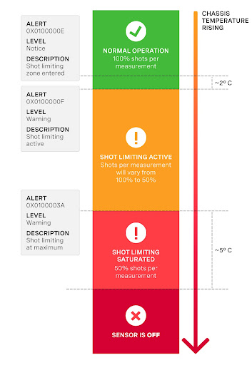
50% shot limiting means 50% of the signal not 50% of the range.
Shot Limiting - Sensors Running on Firmware v3.x and later
Shot limiting is a process by which the Ouster sensor will automatically enter into state to safely prolong the operational performance of the sensor in high operating temperature conditions. There are several different levels of shot limiting that are described in the Shot Limiting Status Flags table.
The sensor has three operating states in order to manage high temperatures:
NORMAL (Status 0x00)SHOT_LIMITING_IMMINENT (Status 0x01)SHOT_LIMITING (Status 0x02 and greater)
In the NORMAL state the sensor will perform to the range and precision specifications of the datasheet. When the sensor reaches a certain temperature, the sensor enters the SHOT_LIMITING_IMMINENT state and issues alert 0x0100000E which indicates shot-limiting will commence in 30 seconds. After 30 seconds have elapsed and the temperature remains elevated, the sensor issues alert 0x0100000F and enters a SHOT_LIMITING state.
In shot limiting state, the sensor reduces power to the lasers in order to reduce the thermal load. While in this state, sensor range and precision may degrade by up to 30%. The sensor will progressively increase shot limiting if the temperature remains elevated. If the sensor reaches its maximum degree of shot-limiting, it will throw alert 0x0100003A.
If the sensor cools down while it is in either SHOT_LIMITING_IMMINENT or SHOT_LIMITING state, the sensor will return to the NORMAL state.
An independent state machine runs for thermal shutdown. When the sensor reaches the maximum operating temperature specified in the table Maximum Thermal Performance, the sensor will enter a SHUTDOWN_IMMINENT state and issue an alert in category OVERTEMP. If the sensor temperature remains elevated after 30 seconds, the sensor will shut down and issue alert 0x0100006B.
Please refer to the Hardware User Manual to learn more about the maximum thermal performance.
Information regarding the shot limiting status is presented as part of the lidar data packet in the Configurable Data Packet Format. Shot limiting status will be a part of the packet header when config parameter udp_profile_lidar is set to one of the following values shown below.
- Single Data Return Format
- Low Data Return Format
- Dual Data Return Format
- FUSA_RNG15_RFL8_NIR8_DUAL Return Format
The following flags are present in configurable data packet header:
Shot limiting status [4 bit unsigned int] - Indicates the shot limiting status of the sensor. Different codes indicates whether the sensor is in Normal Operation or in Shot limiting.
Shutdown Status [4 bit unsigned int] - Indicates whether thermal shutdown is imminent. This can be due to shot limiting being saturated, or due to any other over temperature conditions and depending upon the situation the appropriate alert is generated. When thermal shutdown is imminent, this flag will be set to 1 and the Thermal Shutdown Countdown field will be set to 30 seconds.
Shot limiting Countdown [8 bit unsigned int] - Countdown from 30 seconds to indicate when shot limiting is imminent. When the condition for entering shot limiting is met, the shot limiting status bit is set to 0x01 and the alert 0x0100000E takes effect. At this point the shot limiting counter will be set to 30 seconds and a countdown to initiate shot limiting will start.
Shutdown Countdown [8 bit unsigned int] - Countdown from 30 seconds to indicate that thermal shutdown is imminent. When a thermal shutdown is completed, the alert 0x0100006B will take effect and the sensor will automatically go to the ERROR state and stop outputting data.
The following table describes the codes in the shot limiting status flags, and what mode it corresponds to:
Shot Limiting Status Flags
Appendix
Simple Thermal Model
- Use the sensor CAD from the Downloads page to define the control volume
- Simulate the sensor as a conductive material, such as aluminum, with a single power source.
- Using the sensor product line data sheet to determine the power dissipated inside the control volume.
The power dissipation varies during startup, nominal operation, and in cold ambient temperatures.
OS0/1 Detailed Thermal Model
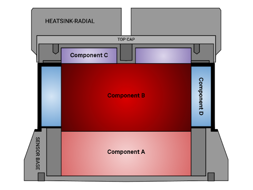
The Thermal Model Specifications table and the cross section above detail the specifications of the Thermal Model. Assumptions for Thermal Model are as follows:
- Use case is to add the Thermal Model to CAD/simulation software to conduct CFD simulation.
- Simulation is not transient, so thermal capacitance of materials and soak times do not need to be accurately estimated.
- Simulation needs to estimate the power dissipation at the sensor’s three external components: HEATSINK-RADIAL, WINDOW, and SENSOR BASE enclosure given various external constraints.
- Internal temperatures of the sensor do not need to be simulated.
- Temperatures and heat fluxes need to be simulated at the control volume surface.
- There is no contact resistance between components of the Thermal Model.
- The Thermal Model assumes 18W power dissipation. This is a conservative assumption for a sensor at steady state conditions at higher temperatures. Sensor power draw is higher during startup and colder ambient conditions. Reference the relevant sensor datasheet for the power draw at startup and cold ambient temperatures.
Thermal Model Specifications
There is no contact resistance between components of the thermal model within the sensor control volume.
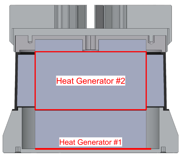
Heat Flux Interfaces
Supplemental Thermal Load Cases
Tables below provides load cases for Rev7 OS0/1 at limited FOV, signal multiplier modes, and higher temperatures. The OS0/1 draws lower power at higher temperatures.
The Ouster thermal team recommends using a simple 18 W total load as a conservative assumption even at higher temperatures when designing a sensor mounting hardware to simplify analysis and add margin to mounting hardware designs.
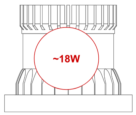
Normal Operation at Room Temperature
Normal Operation Near Shot Limiting Temperatures (53ºC)
Full Shot Limiting Operation Near Shutdown
Shot Limiting and Shutdown Plots (Rev7)
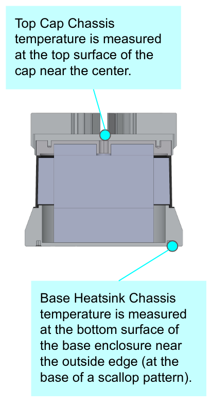
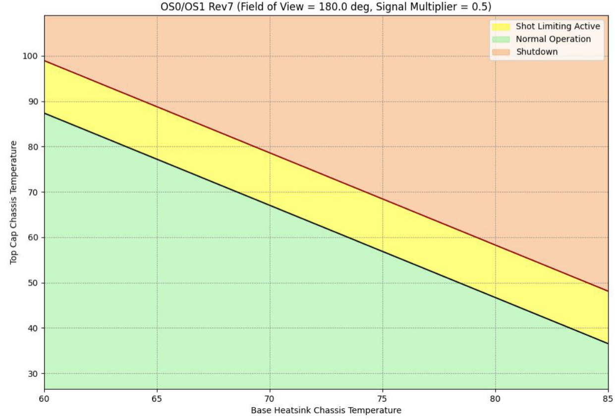
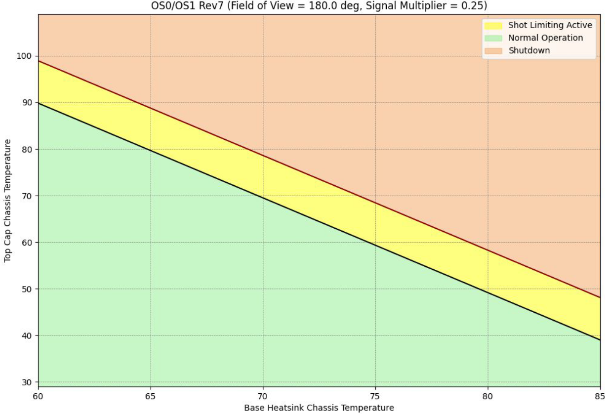
The following graphical representation shows expected shot limiting and shutdown limits based on the base enclosure bottom surface temperature and top cap (top) surface temperature. This data is only available for Rev7 sensors.
The measurement was taken with thermocouples placed at Top Cap Chassis and Base Heatsink Chassis as shown in the image below.
Graphical representation: FOV= 360º and Signal Multiplier = 1

Graphical representation: FOV= 360º and Signal Multiplier = 0.5
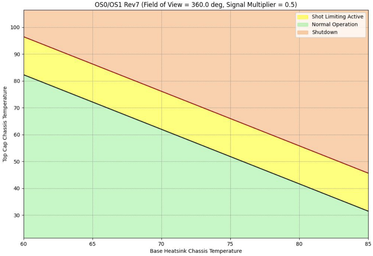
Graphical representation: FOV= 360º and Signal Multiplier = 0.25
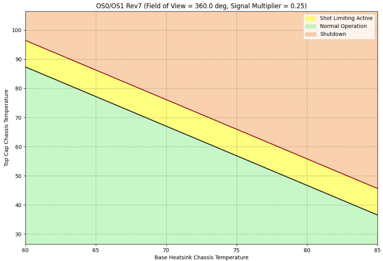
Graphical representation: FOV= 180º and Signal Multiplier = 1
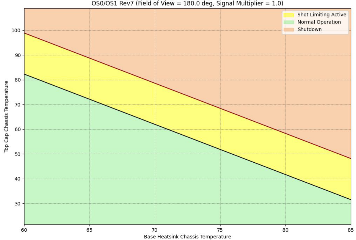
Graphical representation: FOV= 180º and Signal Multiplier = 0.5
Graphical representation: FOV= 180º and Signal Multiplier = 0.25
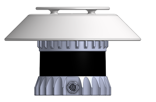
Sunshade Concept Design
We have created a simple Sunshade Concept Design that may help mitigate the solar load. It attaches on top of the modular cap using the existing mounting holes in the modular cap.
-
The modular cap (HEATSINK-RADIAL or -HALO) must remain attached to the TOP CAP of the sensor. The original M3-0.5x5 mm modular cap screws would need to be replaced with longer M3-0.5x30 mm standoffs.
-
This concept design is only for sensors with the modular cap that has the four mounting holes to interface with the TOP CAP.
- 840-101855-03 - Gen1 OS1 with Locking Bayonet Connector
- 840-102144-A/B/C/D/5/6/7 - Gen2 OS0 with Locking Bayonet Connector
- 840-102145-A/B/C/D/5/6/7 - Gen2 OS1 with Locking Bayonet Connector
-
This version is designed not to occlude any beams on a Gen2 OS1-128 with 45º VFOV. Design should be modified to accommodate wider VFOVs (90º) or more shade.
This design is meant to be an inspiration for your design and has not been validated.
The CAD model is available on Ouster Downloads page for you to iterate and fabricate.
Supported Products
The current firmware is supported on the following Ouster products:
-
Firmware 2.5.x
-
OS0, OS1, OS2:
- GEN1: P/N 840-101-XXX-XX
- Rev C: P/N 840-102-XXX-C
- Rev D: P/N 840-102-XXX-D
- Rev 05: P/N 840-102xxx-05
- Rev 06: P/N 840-102xxx-06
- Rev 7: P/N 860-10xxxx-07 (OS2 Only)
-
-
Firmware 3.1.x
-
OS0, OS1, OSDome:
- Rev 7: P/N 860-10xxxx-07
-