

Thermal Integration Best Practices
There are a few considerations when designing your heatsink integrations for your application.
-
Choose a material that has a high thermal conductivity to ensure the heat is efficiently conducted away from the sensor.
-
If possible, the sensor should not share an interface with materials with low thermal conductivities. Materials such as wood (~0.12 W/m-K), glass (~0.935 W/m-K), and rubber (~0.140 W/m-K) have low thermal conductivities. In general, Aluminum alloys are best both for their thermal conductivity and mass properties.
-
Below is a list of recommended Aluminum alloys and their thermal conductivities:
-
-
Ensure that all interfaces are clean and free from debris. Debris and contaminants can reduce the thermal conductivity at an interface.
-
Torque bolts appropriately for the mount material and bolts specified. This will ensure the best thermal conductivity at an interface without damaging the threads. Below is a list of torque values for the sensor by screw size:
-
2 N-m: M3-0.5 mm
- HEATSINK-BASE to SENSOR BASE
- HEATSINK-RADIAL or -HALO to sensor TOP CAP
-
4 N-m: M4-0.7 mm
- HEATSINK-CLAMSHELL top to clamshell riser
-
7 N-m: M6-0.8 mm
- HEATSINK-CLAMSHELL base to sensor TOP CAP
- HEATSINK-CLAMSHELL base to clamshell riser
-
-
Use Thermal Interface Material (TIM) for any irregular or non machined surfaces. TIM usually comes in a paste or pad form; it works to increase the surface area that heat can be conducted through at an interface.
-
Ensure that the sensor is not over constrained if mounting to both SENSOR BASE and TOP CAP. If the sensor is clamped between the surfaces that attach to the SENSOR BASE and TOP CAP, the WINDOW will experience deflection which will negatively affect the optical performance.
- To ensure this does not occur we recommend using a TIM pad to ensure good conductivity while not over-constraining.
-
Ensure your implementation maintains the base and top of the sensor below the maximum chassis temperatures listed in Max Operating Temperatures.
-
To maximize FREE and FORCED CONVECTION, the area around the sensor should be unobstructed.
-
Design the shape of any heatsinks to maximize the surface area for FREE and FORCED CONVECTION while being thick enough to allow the heat to conduct through the material. Below are some recommended features:
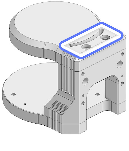
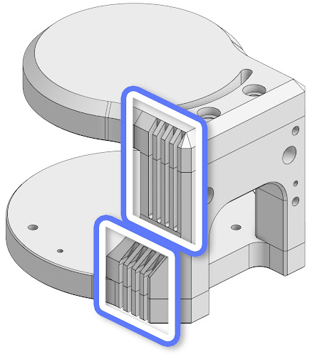
- Whenever possible it is highly recommended to use heatsinks. For special integrations where the HEATSINK-RADIAL and HEATSINK-BASE are both removed, such as drone integrations, it is critical that the thermal alerts are monitored closely. For these types of integrations it is required to use the
STANDBYoperating mode until adequate FORCED CONVECTION (e.g. from flying) is provided. Without heatsinks, if any thermal alerts are triggered, the sensor should immediately be put intoSTANDBYmode or shut off until adequate heatsinking is provided.
If the sensor is consistently receiving thermal alerts due to the removal of the heatsinks, this will void the warranty.
Now that you have some best practices for your integration, we will discuss how to monitor your integration with Thermal Alerts.