

GPS/GNSS Synchronization
GPS/GNSS Synchronization
This guide will explain how to physically connect a GPS to your Ouster sensor and synchronize the Ouster sensor timestamp to an NMEA sentence.
Setting up your GPS/GNSS
It is important to ensure you have configured your GPS according to the manufacturer’s specifications.
The Ouster sensor accepts the following:
- NMEA sentence type:
GPRMConly (future support for other sentence types) - Baud Rates:
9600or115200 - Polarity: Normal or Reversed (
ACTIVE_HIGH1 orACTIVE_LOW2) - Voltage:
3.3 - 15 Vlogic with a minimum drive current of5 mA.- If your GPS can’t meet these minimums you will need to buffer the voltage with an additional circuit. Details in the Digital IO section of the Ouster Hardware User Manual.
ACTIVE_HIGH- Low to high edge as critical timing eventACTIVE_LOW- High to low edge as critical timing event
Once you have configured your GPS, it is good practice to verify the signals using an oscilloscope. This will ensure you have the correct baud rate, polarity, voltage, and message type being output.
Connecting the Hardware
The next step to successfully connecting your GPS is ensuring that you have connected the outputs from your GPS to the correct inputs of the sensor.
Connection using the GPS Port
- Connect the PPS output from GPS to the sync_pulse_in pin of the GPS connector to be plugged on the Ouster Interface Box.
- Connect the NMEA UART output from GPS to the multipurpose_io pin of the GPS connector to be plugged on the Ouster Interface Box.
- Connect the ground output from GPS to the GND pin of the GPS connector to be plugged on the Ouster Interface Box.
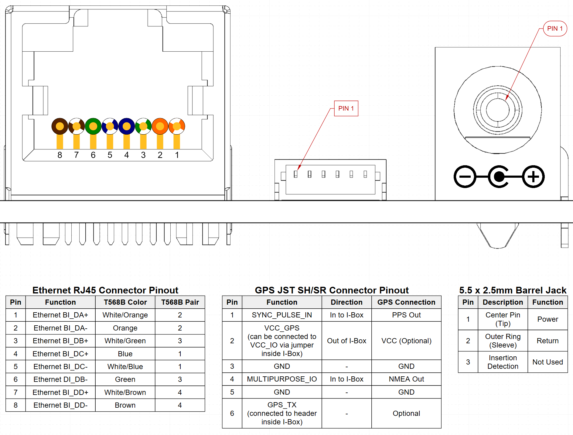
Connection using the Pin out
- Connect the PPS output from GPS to the sync_pulse_in pin of the Ouster Interface Box.
- Connect the NMEA UART output from GPS to the multipurpose_io pin of the Ouster Interface Box.
- Connect the ground output from GPS to the GND pin of the Ouster Interface Box.
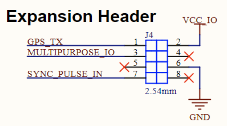
Based on the type of interface box being used please refer to either High Current Modular Interface Box (PCBA PN- 830-103125) or High Current Interface Box (PCBA 830-104249) - Standard.
SYNC_PULSE_IN Interface Requirements
MULTIPURPOSE_IO - INPUT Interface Requirements
Configuring the Ouster Sensor
Please refer to the GPS configuration section in the firmware user manual to configure your sensor to synchronize its timestamp with the GPS.
Support
In case of any questions regarding the contents of this user manual or the configuration of the sensor, please contact Ouster Support or visit Ouster website.